

A perfect mix of automation and human control provides you with a manufacturing process that cuts out time-consuming tooling and delivers castings with high dimensional accuracy.
Our plants in India and the USA use our process and the unique casting technology at our foundry to manufacture both large and small parts at high volume.
Step One —
Pattern Tooling Creation or Wax Prototyping
Wax Prototyping
-
- We perform First Article Inspections (FAI) on parts injected in production tooling to validate the tooling dimensions and release the tooling for production orders.
-
- Any designs validated with prototyping would still need to be approved with an FAI once we create the tooling. If using wax prototyping, wax injection is not required, and the process skips straight to wax assembly.
Pattern Tooling Creation
- Tooling can have multiple cavities, automatic side cores, and ejection pins to allow for faster processing. We can create some undercuts and interior features with automatic side cores built into the tool.
- If geometries cannot be made with side cores from the tool and will have trouble shelling later do to size, shape, and location – ceramic cores can be placed in the tool.
- Wax will fill around the cores and keep the complex space from affecting the desired pattern geometry. These cores can be dissolved later on in the process. Once the tooling has been cut and assembled, it is ready to begin the process at injection.
Step Two —
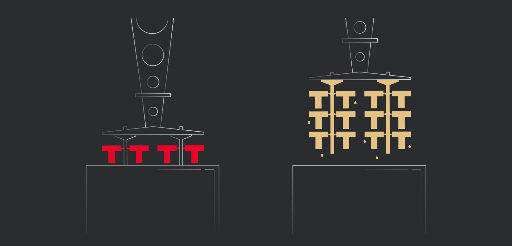
Wax Injection
-
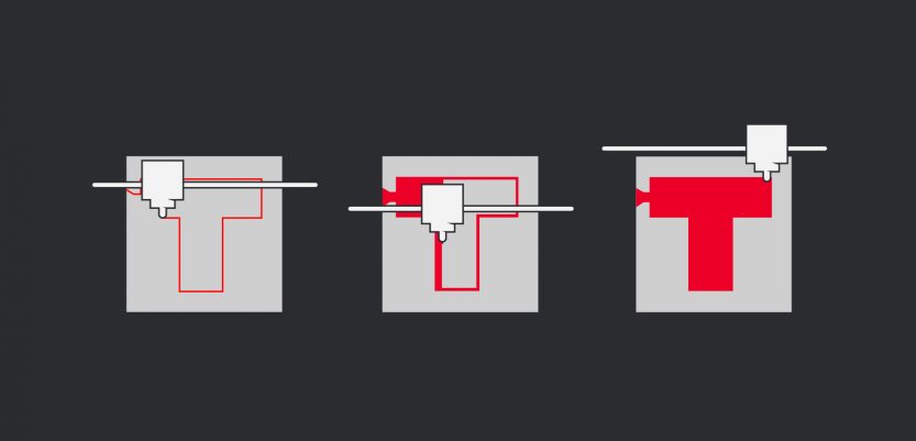
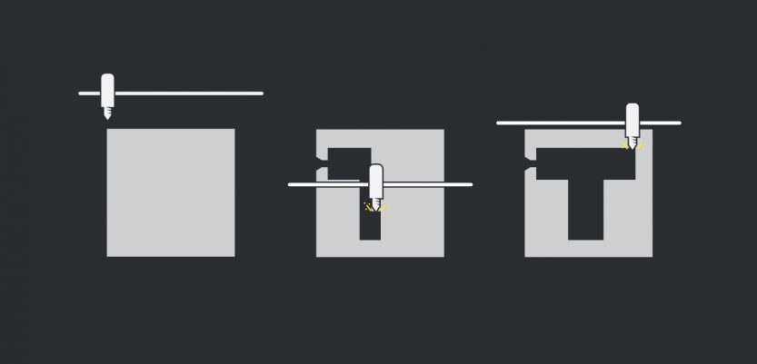
- The wax injection tooling created in the first step serves as a cavity that will be filled with liquid wax, allow the wax to solidify, and produce a positive of the final component in wax.
- Tooling is located and clamped to a stationary table with a moving platen clamping the top half of the die.
- The injection sprue is simply a path that the wax will follow as it is injected through the tool and into the cavity, which will create a positive of the pattern.
- We then melt the wax pellets into a large holding tank located on the wax injection press.
- The tank holds the wax at a liquid and is agitated continuously to ensure a homogeneous mixture of the wax constituents.
- A hydraulic cylinder moves the wax into an injection cylinder to prepare for injection. Once the tool closes, another hydraulic cylinder will push the wax through a heated hose and into the tool via the injection sprue, filling the cavity and allowing the wax to solidify inside.
- Once solidified, the two halves of the die will open, and we remove the wax pattern from the tool. The wax injection operator will close the tool and start the next injection.
- We leave a gate on the patterns which serve as a connection point to the wax runner. At this point, the wax patterns are now ready to move to wax assembly.

Step Three —
Wax Assembly
-
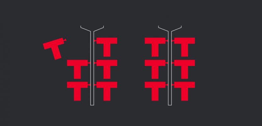
- Once the wax pattern is complete, it’s assembled onto a wax runner. The wax runner will have multiple wax patterns attached to it and will later serve as a metal feeding system to supply all of the individual parts with metal during casting.
- We inject the runners in wax with a process identical to the injection of wax patterns. The only difference is that a metal component is situated at the end which has the wax injected around it; after injection, this metal component has a pin fastened to it that extrudes from the end and can be connected to a hanger plate during shelling in the next process.
- A ceramic cup is also attached to the end of the wax assembly. This ceramic cup will be locked to the ceramic mold during shelling and will act as a funnel for the metal when it is poured in during casting.
- Once the runner is completed, the wax patterns are attached by their gates to the runner. This is done by melting the gate of the pattern on the surface that will interface with the runner and dipping it in a hot melt adhesive wax before pressing it to the runner.
- The waxes will fuse together locking the patterns to the runner. The area around the gate/runner interface will then be welded with a small torch to make a smooth connection all the way around.
- Once all of the patterns are attached to the completed runner, the finished product is called an assembly. The completed assemblies are then ready to move the shelling as the next process.
Step Four —
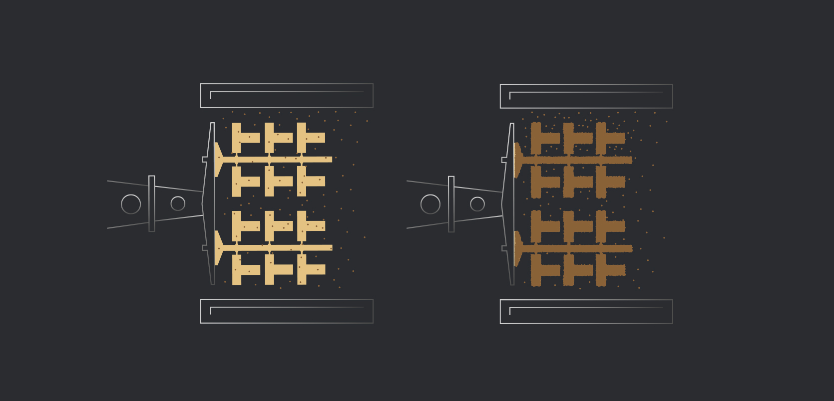
Shelling
-
-
- Shelling is done by dipping the wax assemblies in a series of ceramic slurries and coating them in refractory sands.
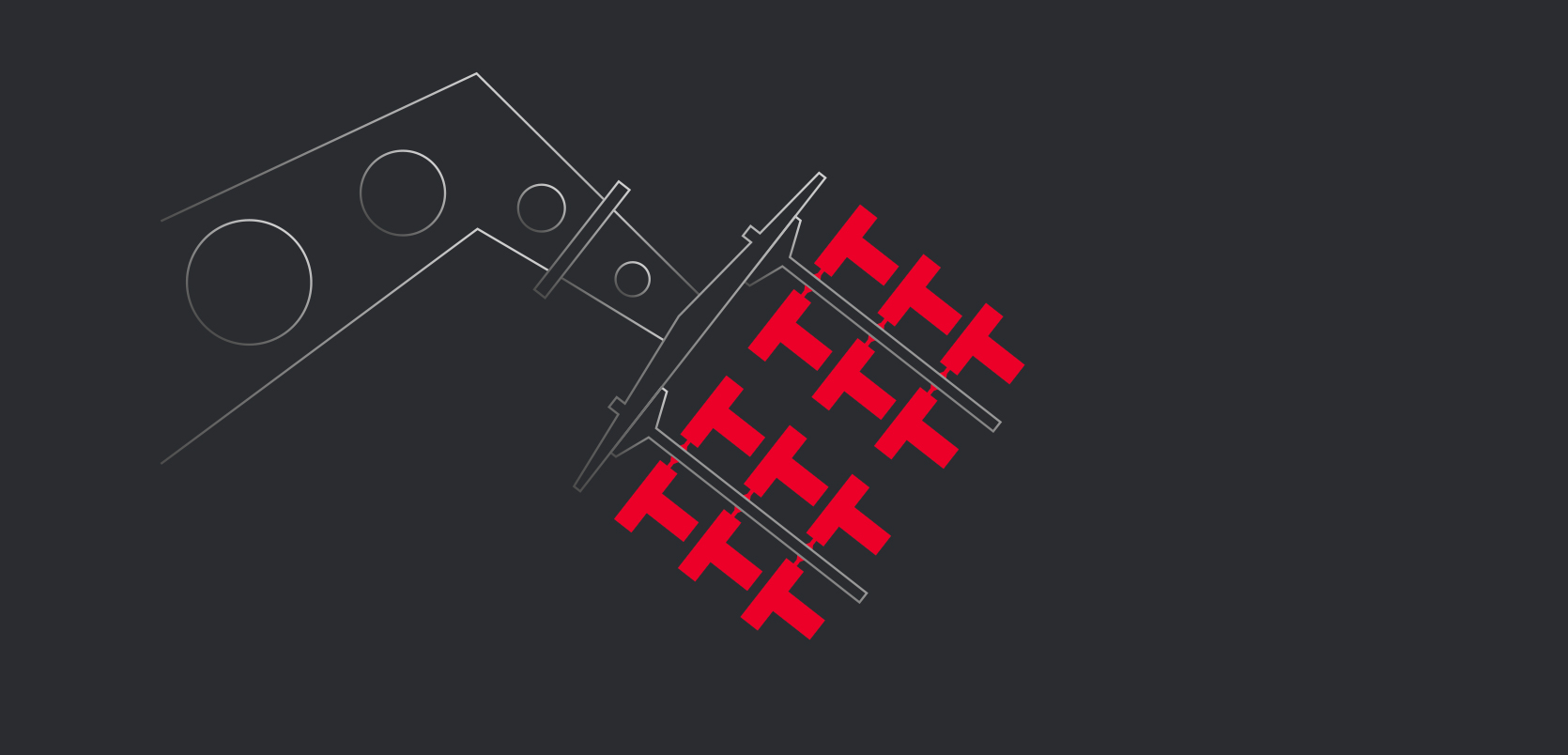
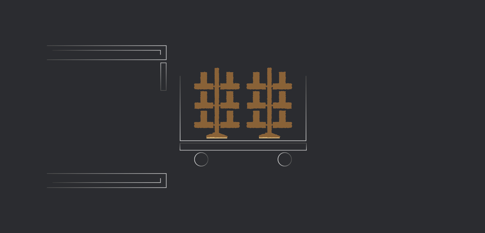
- Multiple assemblies are hung from a hanger plate and pinned in place by the metal components protruding from the top of the assemblies.
- A robot then interfaces with the robot plate, picking up the hanger, dipping the hanger in a ceramic slurry, and removing from the slurry tank and draining while moving in certain positions to ensure uniform coverage and thickness of the slurry before entering a sander.
-
-
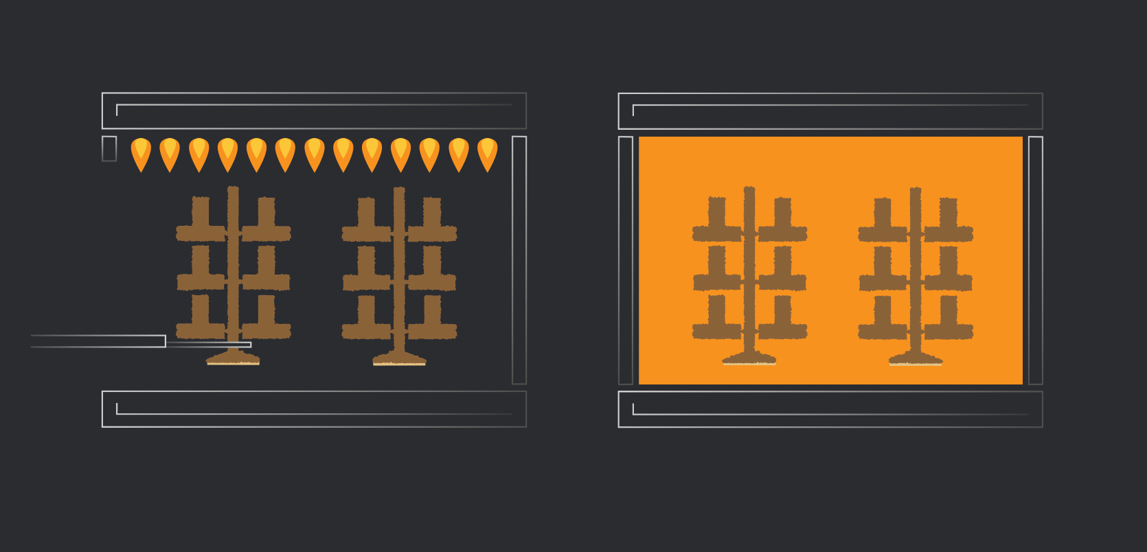
- A sander drops refractory sand over the freshly dipped assemblies while the hanger is rotated and tilted to ensure complete and even sand coverage.
-
- Once we cover the assemblies in sand, the robot will place the hanger on the drying conveyor and go to pick the next hanger for dipping.
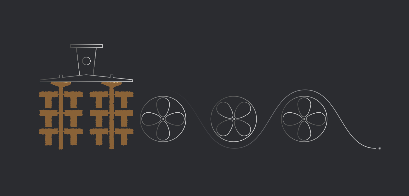
- As the water is removed and the silica particles move closer together, they are eventually stuck together by Van der Waals forces which won’t break, even if moisture re-enters to the mold. Because of this humidity and airspeed must be controlled in the drying room.
- The temperature must also be controlled tightly from injection to dewax to prevent the wax from distorting dimensions or cracking the mold once shelling has commenced.
- A series of ceramic dips will take place with specified dry times in between to ensure that there is sufficient drying of the previous coat.
- The first dip must be able to withstand the molten alloy during casting by not reacting with the metal and also controls the surface finish.
- The consecutive dips add thickness and strength to the shell so that it may hold the liquid metal without cracking or leaking.
- Once the dip sequence and drying times are complete, we unload the completed shells for the robot and ready for the dewaxing process.
Step 5 —
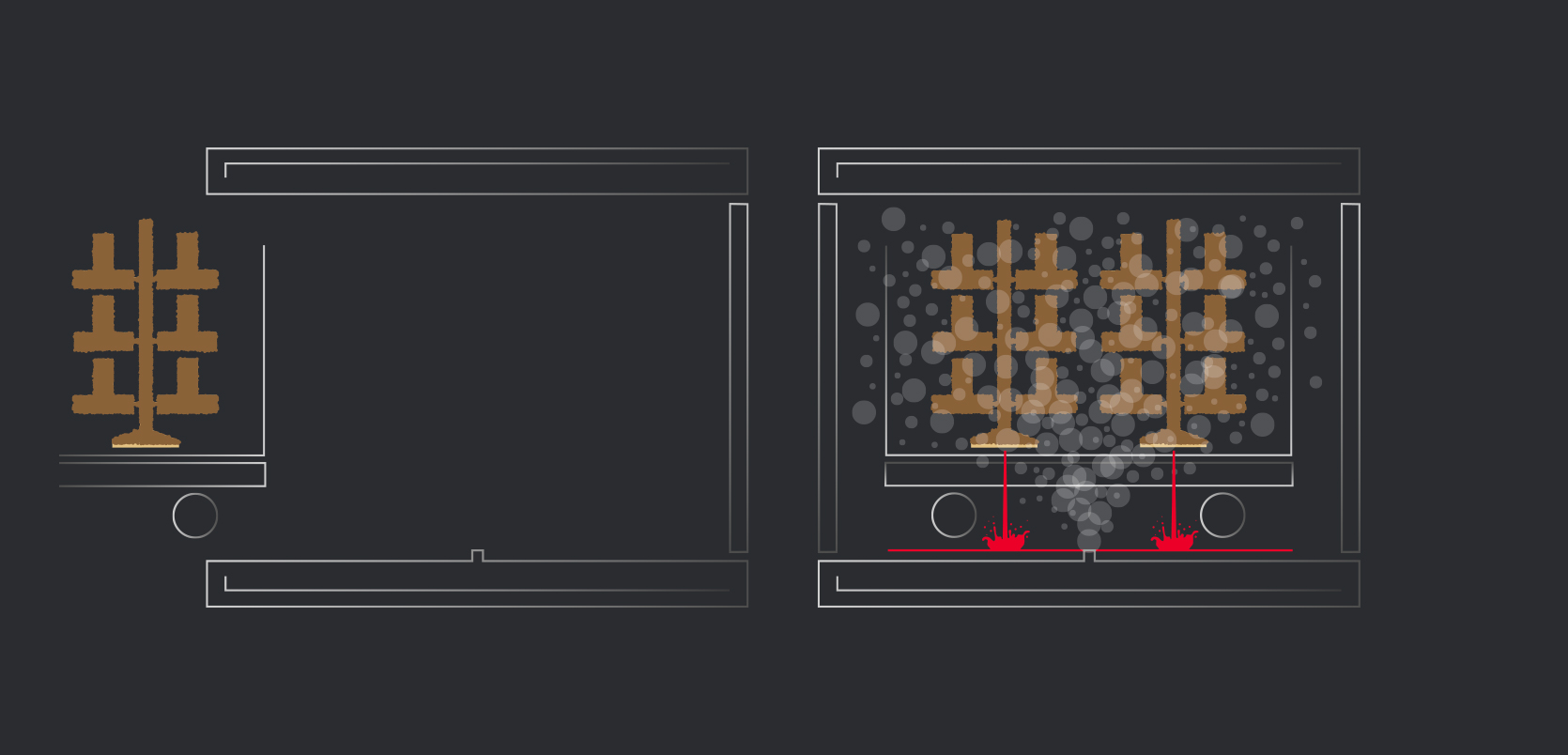
Dewax
-
- Before casting this, the wax must be removed. The wax must be melted quickly so that it does not have time to expand before becoming liquid and rapidly dropping in viscosity. It also must not be burnt out.
- Due to the amount of wax present in the shell during dewaxing, burning out with combustion will lead to amorphous carbon which will not readily burn out and leave deposits in the shell which will later displace metal during casting.
- The parts are quickly loaded into the vessel, a pressure door is sealed, and the boiler valve opens allowing steam to enter the vessel and cause rapid pressurization. This rapid pressurization causes the temperature to quickly rise due to the Ideal Gas Law.
- The temperature increase rapidly melts the wax without the use of combustion. Once the wax has melted out, the pressure of the vessel is exhausted, and we open the door.
-
- The wax that comes out of the shell can be reclaimed and reused after removing water and other impurities from the wax.
- The small amount of wax that remains in the shell can then be burnt out in the next process without the worry for creating amorphous carbon.
- The boiler remains pressurized and we repeat the process for the next batch of shells.
Step Six —
Casting
-
- Upon dewaxing, the shells must be allowed to dry to prevent the rapid expansion of water during heating in the next process.
Heating the shells also gives the liquid metal more time to move through the shells without freezing off before filling the shell cavity.
While the shells are reaching steady-state temperature in the burnout oven, the alloy is being melted in induction furnaces, ready to be poured into the shells.
- Upon dewaxing, the shells must be allowed to dry to prevent the rapid expansion of water during heating in the next process.
-
- When the alloy enters the furnace, a liquid-cooled copper coil with high power moving through it creates an electromagnetic field (EMF). The EMF induces a current in the metal alloy and the natural resistivity of the alloy creates heat which can quickly melt the metal.
- The copper coil is protected from the molten alloy with a refractory crucible which can withstand the harsh conditions that come with being in contact with molten metal for extended periods.
- Once the alloy melts to the desired temperature a few extra operations may occur before melting.
- First, all heats (each new batch of molten alloy) have a sample collected from the bath for compositional analysis. Optical Emission Spectroscopy vaporizes a portion of the metal sample and analyzes the intensity of light at different wavelengths to determine the amount of each element present in the alloy. This process ensures that all heats are at the correct composition for the specified standard.
- Degassing agents may also be added to the melt to remove any soluble gases that may be left in the casting as it solidifies after the pour.
Finally, the slag is removed from the melt so as not to pour slag inclusions into the shell which would displace metal from the desired negative space created by the shell. - Slag is the formation of oxides, nitrides, and other compounds that may form inside the bath as the metallic elements reacted with gases in the air. Once these operations are complete, the heated shell is removed from the oven and the molten metal is poured into the shell.
- The metal is left to solidify in the shell to form the desired metal components.

Step Seven —
Shell Removal
-
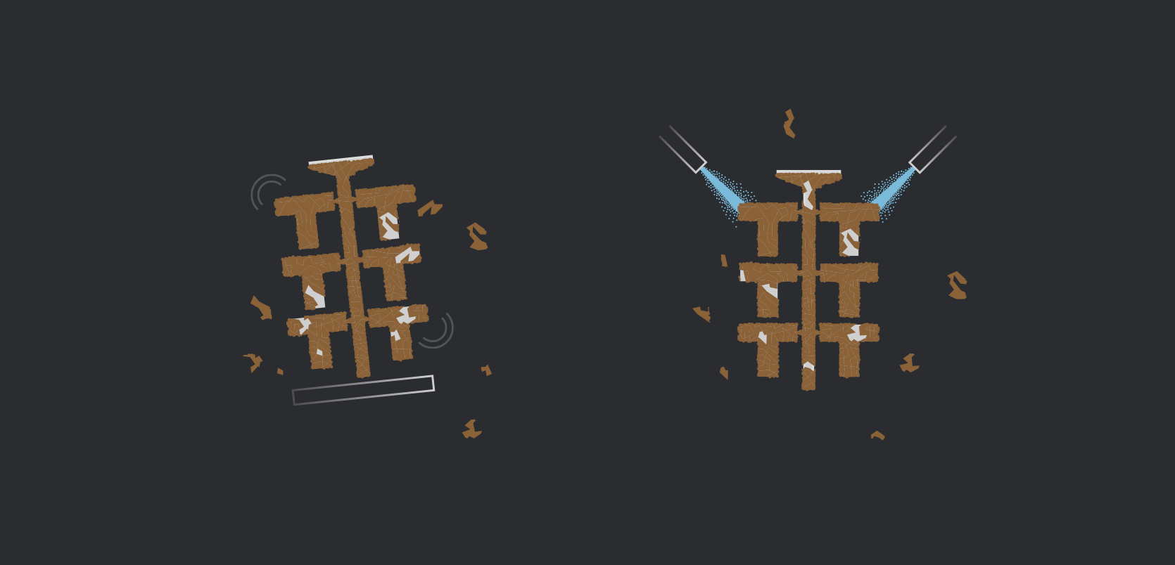
- Once the shell has cooled and the metal solidifies, the shell will begin to flake off on its own. This flaking occurs due to phase changes that occur in the ceramic as it cools.
- The remaining ceramic is removed by imparting vibrations to the metal assemblies or blasting the ceramic off with high-pressure water. Either way, the process is automated.
- The parts are a fixture and either hit on the runner with a pneumatic hammer or fixture so that multi-axis water jets can blast the ceramic off of the castings.

Step Eight —
Cutoff
-
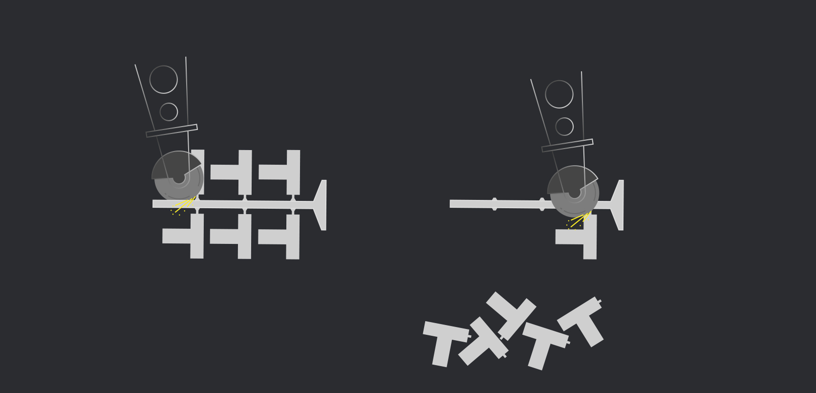
- After the shell has been removed, the running system that parts were attached to has now served its purpose.
- The next step in the process is to remove the parts from the runner, which is done by an automated process in which the metal assembly is fixed in a robotic cutoff machine.
- By using robotics and servos, we manipulatethe assembly so that a saw can be used to cut the parts from the tree.
Step Nine —
Grind
-
- After cut off, an undesirable portion of the gate will remain on the final part. To remove this, manual or robotic grinding can be utilized to remove material and leave only the desired component geometry.
- The material removal is done with the use of a belt grinder equipped with coarse grains for maximum material removal.
- This is either be done by manually manipulating the part or placing multiple parts in a grind fixture so that it can be shaped and ground by robotics.
- In this case, an operator simply loads the parts onto a fixture, runs the cycle, and removes the parts when complete. The operator repeats this cycle on consecutive parts.
Step Ten —
Finishing
- Once grinding is complete, the casting is now left in the desired shape of the final cast.
- There are a few finishing operations necessary to make the part to acceptable quality for the customer. If any defects on any of the castings are present, these defects can be cleaned up with the use of hand finishing tools.
- If any positives are present on the part they can be ground off. Negatives can we welded if allowed by the customer’s casting specification.
- If the parts need straightening to meet specific GD&T callouts, hydraulic straightening presses can be used to put these features back into tolerance.
- After all other finishing operations are complete a final blasting operation takes place to bring the parts to their desired surface requirements.